We have developed a controllable trailing edge flap which can be deflected by controlling the pressure in suitable designed voids within the elastic flap. A prototype flap has been designed for a 1 m chord NACA 0015 airfoil section and the flap has a chord length of 15 cm. The flap manufactured in silicone rubber has a number of conical reinforced voids in chord wise direction. Static and dynamic test of the flap in a test rig has been performed.
Later in 2009 the flap wasmounted on a NACA0015 1 m chord airfoil section model with pressure tabs and tested in a wind tunnel.
A number of numerical studies within the last few years have shown a big potential for reduction of dynamic aerodynamic loads using a trailing edge flap. The studies indicate that much faster control can be obtained with flaps compared with normal pitch of the whole blade as the mass of the flap can be made substantially lower than the blade. The big challenge is however, how to obtain the flapping mechanism.
A number of different proto type flaps in silicone rubber have been manufactured at the Fiber Laboratory in the Materials Department at Risø DTU. Different void configurations as well as silicone rubber types were investigated.

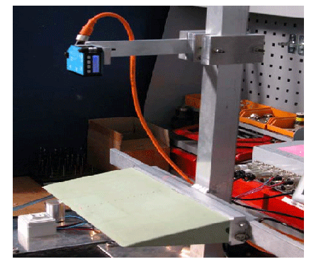
The different prototype flaps were tested in a rig where the deflection at different chord vise positions were measured with a sensor mounted about 0.5 m above the flap. Pressurized air was used as fluid medium.
Robust design of rubber
In 2004 Risø DTU applied for the first patent for this basic technique of designing a flexible, movable trailing edge for a wind turbine blade. Since then there has been a significant development with regard to the project. By means of so-called "Gap-funding" provided by the Ministry of Science, Technology and Innovation and by the local Region Zealand it has been possible to develop such ideas into a prototype stage.
Profile section with a controllable, flexible trailing edge, which is controlled from measurements of inflow to the blade using a Pitot tube attached to the front edge of the blade section (left) or a trailing edge operated from the load on a small profile section mounted in front of the main blade (right).
Test in a wind tunnel
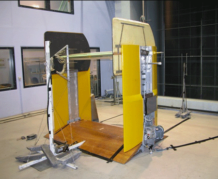
The test layout consisted of a two meter-long piece of a wind turbine wing, which at the rear had mounted 6 rubber trailing edge flaps, which was subsequently glued together. Inside the wing, there was a hydraulic system to control the flexible silicone material that the rear is made of. On the front of the wing several types of sensors were attached, which measured the wind direction and strength before hitting the wing.
A view of the trailing edge flap which in the present experiment constitutes 15% of the total chord length
.

A view towards the inlet of the wind tunnel.
It has until now been the major focus to demonstrate and verify operation of law, but the test shows that it is a robust and reliable model that can withstand strong winds, and the next focus will be on optimizing the design and test it in a prototype on a full-scale size wind turbine
Acknowledgement
The development of the CRTEF system has been supported by the GAP funding at Risø DTU and the local community Region Sjælland.
The flap technology has been further developed in two projects:
- INDUFLAP - an EUDP 2010-II project “Industrial adaptation of a prototype flap system for wind turbines” carried out in the period 2011-2014. Partners DTU, Rehau and Hydratech
- and INDUFLAP2 “ Full scale demonstration of an active flap system for wind turbines” carried out in the period from 2015 to 2019, funded by EUDP 2015-I. Partners DTU, SiemensGamesa and Rehau
To learn more visit Induflap